
Floor plan editor
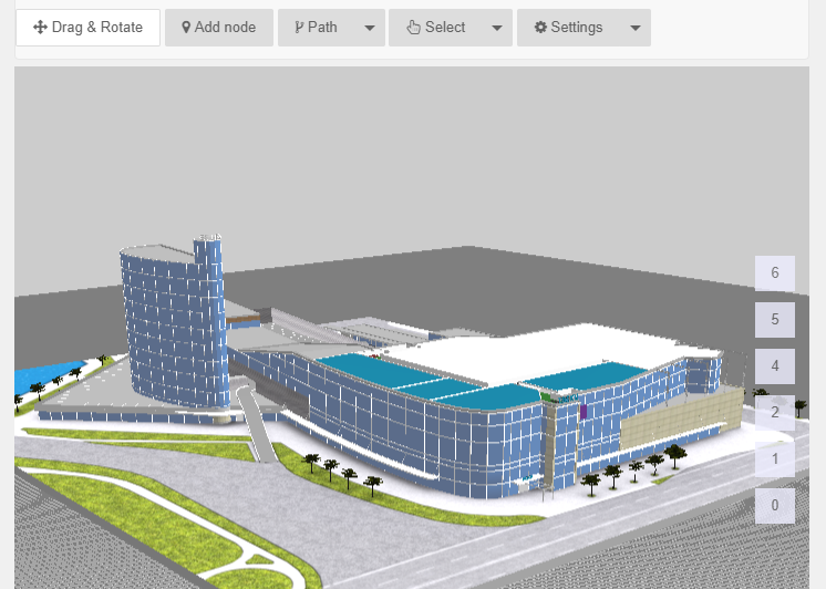
You can open 3D floor plan editor by clicking “Editor” from main menu. Editor loads all the 3D floor plans and with editor you can map locations to the maps. For better performance editor doesn’t show the effects (skybox, anti-aliasing etc.). Loading editor might take some time.
After editor has loaded you’ll see the buttons for basic functionality on the top, the floor buttons are on the left side of the editor window:
In editor you can change the view by
- Mouse scroll-wheel – zooms in and out
- Left click and move the mouse – rotate the building
- Right click and move the mouse – move the building
There are also help texts for what you can do with editor and how to use mouse buttons.
Adding new node
Node is a point on the map. Nodes can be used to mark the locations (kiosks, shops, toilets, stairs, sensors etc.) to the map, create navigation paths and connect parts of the 3D model (ceiling, stairs) with locations.
To add a new node select “Add node” button from the top menu in editor window. Then click with left button on the map, where you would like to add the node.
You’ll see a new node appear in the place you clicked.
Managing nodes
For selecting a node click “Select” button and choose “Select node” from drop-down menu.
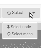
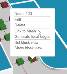
After clicking on a node a green borders appears around it and node options will appear.

Here you can edit or delete the selected node, generate local edges, set or show kiosk view. You can also delete a node with “Delete” key on your keyboard.
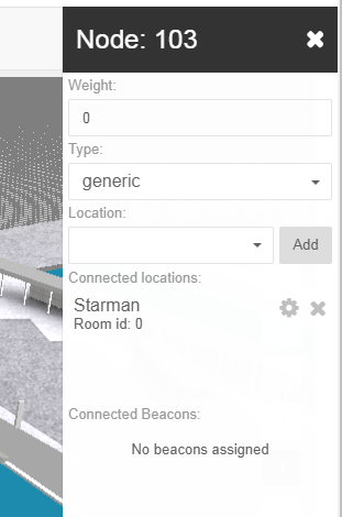
After clicking “Edit” you can change nodes weight, type and add a location to it.
To move the selected node, you’ll have to left-click on the node and drag it to desired location.
It is possible to add many locations to the node. This means that there are many locations in this point in map, where the node is.
To add a location, select a node, choose “Edit” and open the drop-down menu under “Location”. Choose a location and press “Add”. Added location will appear under “Connected locations”. Repeat for adding another location. The node that has a location added turns red.
After the node has a location added, it can be linked to mesh.
Linking meshes will give you 2 functionalities:
- When using 3D Wayfinder users can click on floors, escalators etc. and they can see connected location info
- When selecting location from menu, 3D Wayfinder can highlight the mesh, to show where the location is on map.
To link a mesh to a node, first select the node, choose “Link to mesh” from options (it appears after the node has been connected to a location).
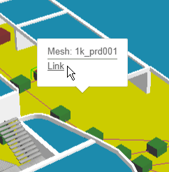
Then click on the mesh you want to connect, chosen mesh will turn yellow, and choose “Link”. This will save the connection.
If you are using wayfinding kiosks then you would like to load 3D Wayfinder with the specified view to the map, depending where the kiosk is in building. “Set kiosk view” button sets the kiosk view to the node the way you are looking the map in your editor and “Show kiosk view” show the view.
Creating paths for wayfinding
To find the shortest path from one location to another you need to connect the 2 locations with a path. To create the path the way people are walking in the building you’ll also need to create navigation nodes between the 2 locations.
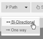
For creating paths click on the “Paths” tab on top of the editor window and choose “Bi-directional” or “One way”. “Bi-directional” means that this path can be used to navigate both back and forth, “One way” is useful for places like escalators, where you can go only one way and need another way to come back.
Connecting nodes with path
You can connect 2 nodes by clicking on them with path tool selected.
To connect node to other nodes near it you can use button “Generate local edges”. The node has to be selected first. This will connect the node with other nodes that are near it.
Path tool
Click the “Path” button on the top of the editor window and choose “Bi-directional” or “One way”.
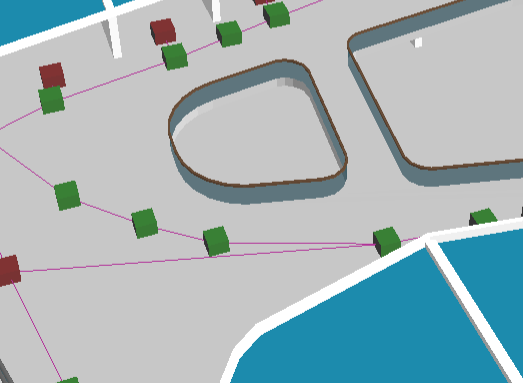
Now you can select the first node, from where you would like to start creating path. Now if you click somewhere on the map a new node will be added and connected with the previously selected node. Nodes will be connected with a line:
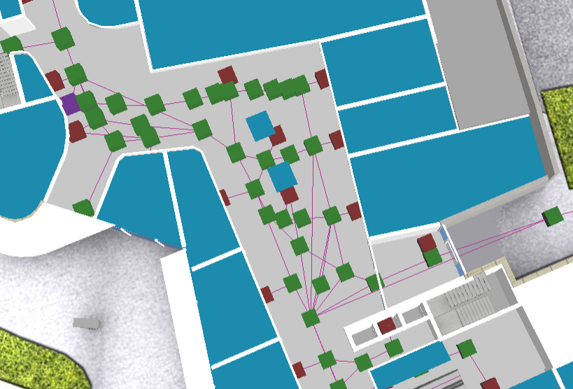
This means that in real life users can move from one node the other. So pay attention not to connect directly nodes that are not directly visiblle (there are objects or walls between them).