This tutorial will show you how we use bevel in some of our 3D wayfinding maps.
There are 3 main options in Blender to get the beveled edge look.
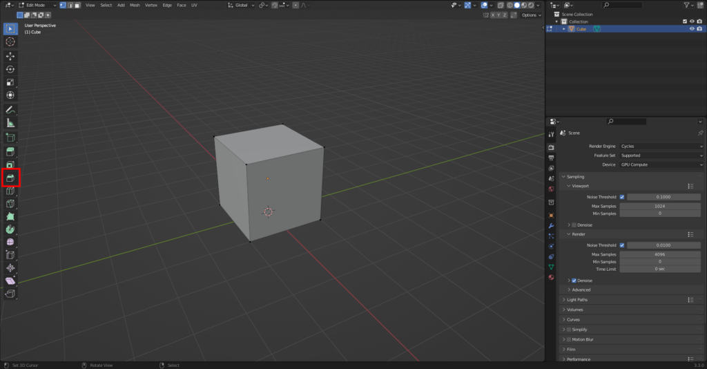
First is the Bevel Tool
Select the object you want to bevel in Blender, go to edit mode then select the bevel tool from the left row (press T key to enable it if it’s hidden).
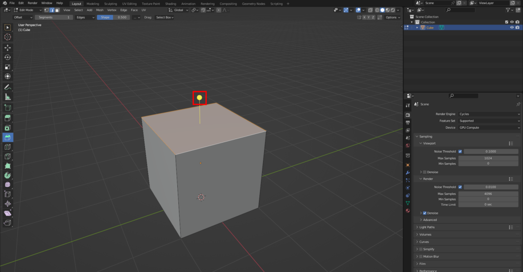
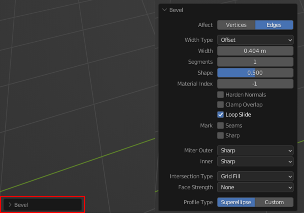
Select the edges you want to bevel and click and drag the yellow circle to adjust bevel amount. When satisfied you can further fine tune it in the toolbar that’s located on the left bottom side. Faster way to add the bevel tool is to use shortcut ctrl + B and adjust amount with mouse. Press right mouse button when you are done.
Second, Less Common Way is to Use Extrude & Scale
Select the object you want to bevel in Blender, go to edit mode then select the face(s) of which edges you want to Bevel. Extrude (press E key) the face(s) on z axis (press Z key) and move them up a bit. Then scale them down (press S key) until you have the desired look.
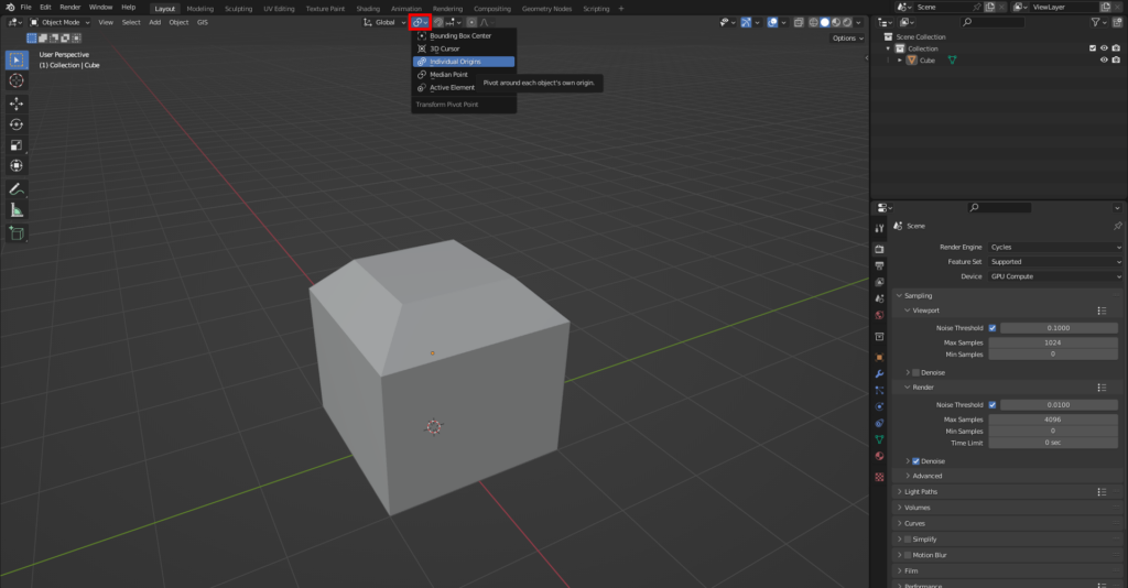
WHEN YOU ARE BEVELING MULTIPLE OBJECTS AT THE SAME TIME MAKE SURE TO CHANGE TRANSFORM PIVOT POINT TO INDIVIDUAL ORIGINS.
Final and Nondestructive way
Nondestructive meaning that the bevel doesn’t fundamentally change the mesh. This also means that you have to check the apply modifiers button when exporting mesh.
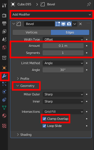
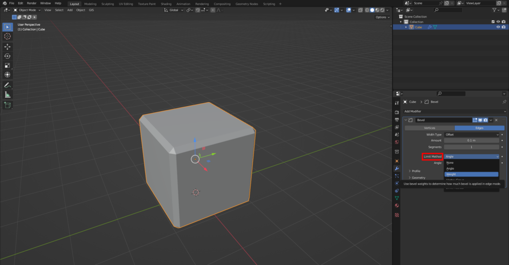
Go to modifier properties (blue wrench icon) and click add modifier then click bevel. Leave segments to 1 and adjust the amount to your liking. If it doesn’t work right away then go to geometry tab under bevel and turn off clamp overlap and correct the amount.
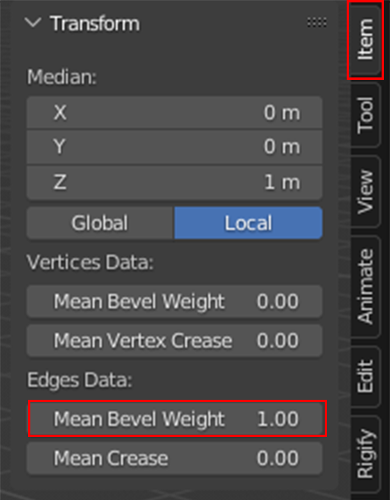
To add bevel only to those edges that you want, change limit method to weight. Go to edit mode, select the edges you want to bevel then open right sidebar (press N key) under tab “item” change the mean bevel weight to 1.
Before Adding The Bevel Modifier it’s a Good Practice to do and Check The Following
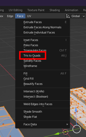
1. Mesh needs to be clean and use only quads.
Removing tris– select everything– go to edit mode– make sure everything is selected– then use ALT + J or on the top bar go to Face– “Tris to Quads”.
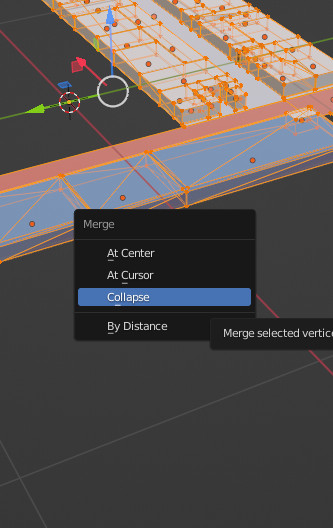
If there are still some tris then have to manually merge them. Select the vertices and press M– “Collapse”. Second option is to just remake the whole box.
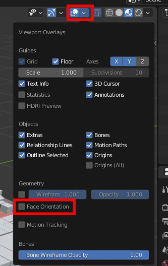
2. Make sure that normals are correct. Check this by going to “Show Overlays” and enabling “Face Orientation”. If Everything is blue then move on to step 3.
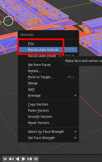
Fixing normals– select everything– go to edit mode– make sure everything is selected– use ALT + N– “Recalculate Outside”.
If some are still red then you have to manually select the red ones and use “Flip”. (ALT + N)
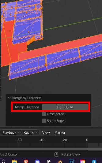
3. Make sure there are no Doubles.
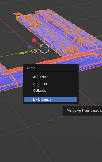
Select everything– go to edit mode– make sure everything is selected– press M then click “By Distance”– open the little box on the left corner of the screen– set merge value to 0.00001 m
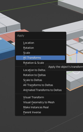
4. Make sure Object scale is set to 1 on XYZ.
Select 1 object– use shortcut CTRL + A– click on “All Transforms”. Do the same for every object.
How are 3D map models made in Blender? Here is a step by step look.You find detailed blender modeling tutorial with videos and specific guidelines.
BLENDER MODELING TUTORIAL GENERAL GUIDELINES
Maintain a clean quad topology and keep poly count low, no need for edge beveling and subdivisions, when the situation does not require it.
The floor, outer walls, inner walls, details, locations, stairs, elevators, locations and greyed out areas must be separate objects, please do not combine them into one.
Its also recommended to group objects of the same kind and name them accordingly.
1. SETTING UP THE SCENE AND MODELLING REFERENCE
Before starting the model make sure you have references ready.
Create JPEG or PNG files from the reference DWG’s or pdf’s.
If the buildings have multiple floors, make sure that the images have the same dimensions and the floors align with each other.
1.1 SETTING UP THE SCENE
Start by setting up the folder system for the project and adding the reference images into this folder system, then prepare the scene for modelling by setting the units( make sure units are consistent throughout the project). We use SI units( metric units), usually meters.
Now you can either create the basemap itself first, based on the provided references or you can create a simple rough layout for the building placement and replace it with a basemap later, based on the provided DWG and pdf references. For following examples, I took the rough layout route. Make sure the rough layout texture has dimensions relative to the upcoming basemap and is placement is roughly the same as it is intended to be intended to be on the basemap.
Add a plane into the scene and make sure it is at center of the scene. I usually scale it larger, for the sole reason of dealing with numbers with less decimal spaces. It can be made larger by either adjusting measurements, scaling in object mode( after which I apply the scale for a clean model), or scale in edit mode.
Now apply material and name it basemap and apply either the ready made basemap or the rough layout texture.
From top view, add floor reference image as an reference image, and align it to the rough layout texture and hide the basemap from view.
2. STARTING THE MODEL
Start by creating the floor plane, begin with the area that is not aligned straight, rotate the plane in object mode, by doing so, there will be a local transform embedded into the object, it will make things easier later on (Do not extrude it thicker, if the z fighting makes it necessary that it can be done later, when the modelling is complete, the reason being that all cutting and editing operations are easier to do with a plane ), name it.
Select the border edge, extrude it, separate it into a new object, name it outer wall or (OW), clear out subdivisions for a lighter model.
Add solidify modifier( No need to apply it), and make sure the direction of thickness goes outward and even thickness is checked.
3. CREATING INNER WALLS
Select Outer wall, duplicate a face, and separate it into a new object, name it Inner wall or IW.
Adjust the modifier settings and object height for variety within the model (optional).
From top view and transparency on, select the vertices and extrude them to create corners.
For visibility, you can select edges and mark them sharp.
NB! Make sure that corner combines only two faces, for the solidify modifier to work smoothly.
Duplicate faces in edit mode for additional walls.
Make sure the walls align properly, by using snap settings and limiting transforms to global or local axis.
Make sure the solidify modifier thickness direction is consistent, change face normals (Alt+N) if not.
4. ORGANIZING SCENE
Create a new collection and name it Floor_0 or something of similar nature.
Select basemap mesh, outer wall, floor mesh, and inner walls and add them to the collection by manually dragging them there in the outliner, or by pressing M in the active view.
Create a new collection and name it reference, add reference image into that collection.
5. MAKING DOORS AND OPENINGS
Select the object (Inner wall or outer wall) and in edit mode use loop cut (Ctrl+R) to divide polygon where necessary, and use edge slide or regular transforming to move it to the right place.
Delete the polygon from between said edges.
With solidify modifier active and not applied, the new door opening will not affect the thickness of wall.
6. STAIRS AND ELEVATORS
No limitations besides low poly count.
Easiest way to populate the scene with stairs, elevators and escalators in to finalize one and then duplicate it.
Therefore make sure that the model is to your liking, it has material applied and when using textures, make sure the object has UV’s.
Add a collection into the floor_0 master collection and name it accordingly (stairs, elevators, escalators).
Make sure the object is within the collection, then duplicate it in object mode, use reference to place them.
7. NEW FLOOR
In the outliner, right click on the floor_0 collection and duplicate it, rename the duplicate into Floor_1 and for clarity I recommend to rename other collection within that as well.
In the outliner right click on the duplicated collection and select hierarchy.
Move it up on the z- axis so that the new floor sits directly atop the lower floor. It can be done either by constraining movement on the z axis and using snap settings, or by constraining movement to z axis and inputting the height of the object „Outer wall“( if you do not remember it then select the outer wall on the floor_0, go to edit mode and for example select one of the upper horizontal edges. Press N and look for the global position of the z axis).
Toggle of the visibility of floor_0 collection in the outliner and select the reference plane, select its object data properties panel and change the reference image from floor_0 to floor_1, if you set up the folders properly than the image should be in the same place.
Make the necessary changes and rebuild what must be rebuilt.
For example cutting in the openings for stairs and escalators etc. If quad topology was maintained then loop cuts work well.
Repeat for other floors.
8. EXPORTING
If the scene is organized then everything should be in right collections.
In the outliner, right click on the floor master collection (floor_0, floor_1…) and select hierarchy.
With the selection active, go to „file“, „export“ and then choose FBX format.
Check the box on „Selected objects“ and change scale value to 0.1.
Create a new folder into the folder system, name it export and add the date of export into the name. Whenever changes are made, create a new folder for the exported files.
Name the file and repeat with other floors.
When its necessary to share the whole project, pack all external data into the blender file from „File“, „External Data“.
Then zip and send the master folder of the whole project.
9. CREATING UV’S WITH MATCHED SCALE
Select floor meshes from all floor collections and isolate them with Shft+H (Alt+H to make everything visible again).
With active selection go to edit mode and make sure all faces are selected.
Open up UV editor split view and in 3D viewport go to top view.
With the selection active, press U while in viewport and select „project from view“.
Select and scale the UV’s if necessary.
In case textures need to be custom made in a another software, select one floor mesh, go to edit mode and select the faces in UV editor and export out the UV layout, it can be used for precise texturing. Repeat with other floors.
10. CLEANUP
Add a large cube to the scene and make sure it is in the overall scene collection, not in one of the floor collections.
Make sure all collections and objects are visible.
Select the cube and assign one of the dud duplicate materials to it.
With the cube selected, press Shft+L and select material, that selects all all objects with that material on it, press Shft+H to isolate selection.
Now apply the correct material to the cube.
Select all the objects with the dud duplicate material and then add cube to the selection, press Ctrl+L and select material. The last object in selection determines the material.
Number of material channels and their order is of importance in that operation. If objects with dud duplicates have multiple material channels and Cube has only one, then it changes only the first channel of the objects, if the cube has two then it changes two channels in the same order. Therefore if every object has only one channel, then it works smoothly, but if there are multiple channels and the dud duplicates are not in the same order then it requires some further steps- But in this case it is easier to change the dud duplicates manually on each object, after the selection step (step 4 of this tutorial).
When the changes are made, delete the cube.
On the top ribbon of outliner, navigate to „Orphan data“ and then click Purge.
Now duplicates have been removed from the scene.
As always we are pleased to help you for creating a wayfinding solution for you or your customer. If you like us to make the maps, please also look our floorplan campaign and don’t hesitate to contact us.
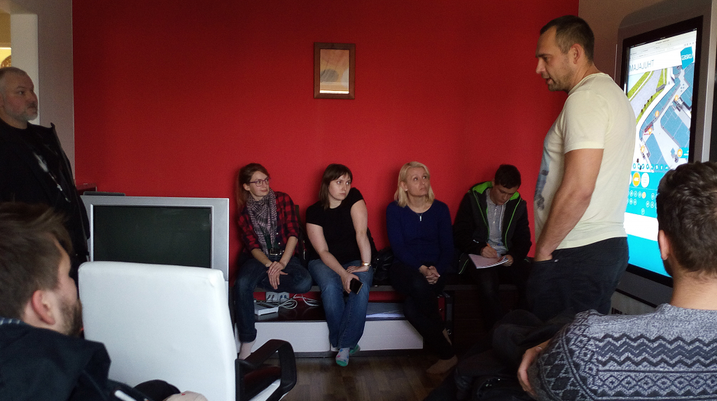
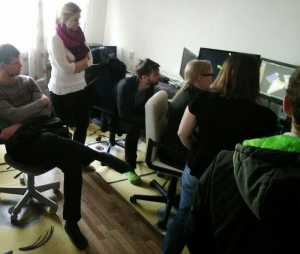
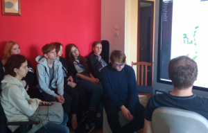
Our office was really crowded last week when we had visitors from Tartu Art School. More than 20 people who have just started their studies to become 3D modellers.
Tartu Art School is the only school in Estonia that teaches 3D modelling and visualization as a vocation. As a part of their curriculum the students visit different companies to see how their skills could be used in the future.
Since 3D models have such a big part in our work, it is also important for us to introduce our company to potential future employees or users of our app.
So we talked about what we do and how we do it and how students could use our product. 3D Wayfinder is currently used for mostly way-finding applications. But that doesn’t mean it couldn’t be used in variety of cases. It’s also perfect for presenting architectural models or – why not – make a virtual art gallery.
It is interesting and useful for us to see what kind of applications the students can find for 3D Wayfinder. So we can make it more flexible and beneficial for a wider range of customers.
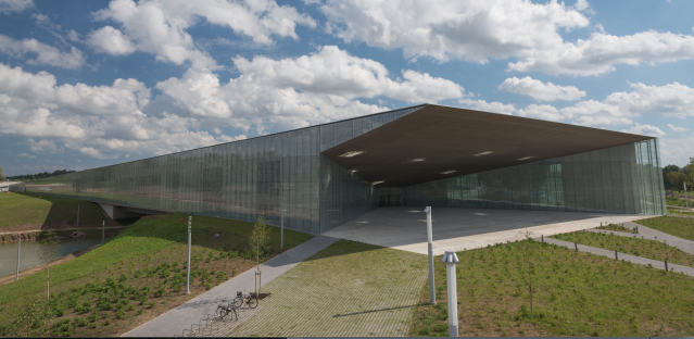
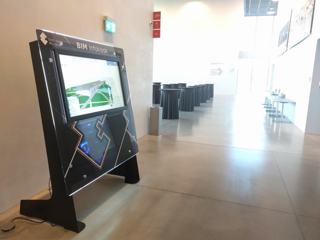
3D Wayfinder is now being used for Building Information Model (BIM) applications. By creating BIM kiosk software for Estonian National Museum we have added many new and useful features to our software and improved the performance for larger models.
Estonian State Real Estate Ltd ordered Building Information Model solution from us for recently opened Estonian National Museum. Now the visitors can easily explore the 3D model of the whole construction. Also they get the overview of the building by all the details.
What is BIM applications?
BIM model is a digital equivalent of the building. It can contain everything from doors to electric fixtures. Although BIM applications technology and methodology is more common in the design of the building. It has large potential benefits for buildings management and maintenance phase.
Estonian National Museum’s new building is meant both for exhibitions and scientific work with net area of 33 879 square meters. We received a model of a building made with Revit, Autodesk software for BIM. It contained highly detailed information – e.g. all the pipes – so it needed a lots of simplifying.
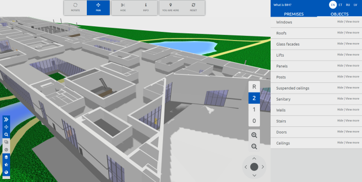
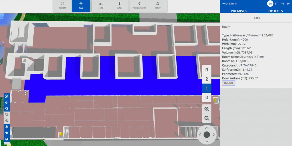
After the adaptations we still had a huge file with close to 12 000 separate elements. It is the largest model we have had in 3D Wayfinder. It was also the reason why we changed the logic of initializing POI data to make the loading of large objects faster.
Table view for all objects in BIM model was done by using Spreadcell. Spreadcell has easy upload from MS Excel files and it provides table-view, sorting etc by webservices (in JSON format). All the objects are divided into separate groups so the final user can choose what do they want to see, hide or find.
Kiosk design
We also built and designed the kiosk from scratch. Since most of the modern kiosk hardware is only enough for showing advertisements or 2D wayfinding plans. The kiosk is equipped with a landscape LCD screen, a touch panel and a dedicated graphics card. It makes kiosk suitable for applications that require greater graphical computing capabilities.
3D Wayfinder application helps to make BIM useful for those who have no access to specific softwares themselves. For example we can integrate BIM with different management softwares. Also add the ability to write comments. In this way we make it easier for different parties to collaborate on centrally shared model.
We have listed some guidelines for creating 3D models, that look nice and run smoothly in web-browsers.
3D Wayfinder uses regular 3D models, so there is no special format or way how the 3D floorplans should be modeled. As 3D Wayfinder works in web-browsers through WebGL technology, then in order to get better results the 3D models should be optimized. Read below for some useful tips and tricks on optimizing 3D models for the best performance.
For example keep the 3D geometry simple and use textures, that can be repeated:
An important element of 3D floorplans are different kinds of vegetation (trees, bushes etc.). They help to make the floorplans look more life-like and in some cases are also important for navigating on the map. It is easy to use transparent textures on the simple planes, just never model out the leaves or branches:
With 3D it is possible to create really life-like buildings, but when using 3D for maps, it is always good to keep the models simpler. For this we suggest removing un-important furniture and making the walls as low as possible without losing the general idea of the height of the room. This way the visibility of the visualized path is far greater.
You find the full list of guidelines for creating 3D models are added 3D Wayfinder page here.
Until now all the materials in 3D Wayfinder have been replaced with each 3D model update. Now it is possible to keep the materials and their attributes’ values. This will save a lot of time, when creating a nice-looking 3D wayfinding application. See how to separating materials from geometry.
We have added a small feature to our 3D model converter. That enables to replace the 3D models without overwriting the materials. This means, that all the changes that were made in 3D Wayfinder for the purpose of tuning materials, are not lost when replacing 3D models. See it in user manual.
3D modelling software packages are different and the way 3D models are exported also varies. In most cases you need to change the color of the materials (diffuse and ambient color). After the creation of the model to get good looking 3D floor plans. We are now supporting specular shader, transparency etc. that might not come directly from the converted models. All these material attributes can be changed in 3D Wayfinder, but these values were replaced each time the geometry was updated. Now there is the option to keep the materials and their values, when replacing the 3D model.
At the same time we have added ambient attributes to each material when uploading the 3D model for the first time or when replacing the model. So there is no need to enter the “ambient” attribute anymore, just change the color.
3ds Max models cannot be used directly in 3D Wayfinder, as .max format is closed file format and our importer doesn’t support it. But exporting 3D models from Max is not complicated.
3D Wayfinder supports following formats for 3D models: .fbx, .dae, .lwo, .obj and .3ds. But as we are using ASSIMP for model converting it is possible to try also other formats. With 3ds Max, we recommend to use .fbx or .dae formats.
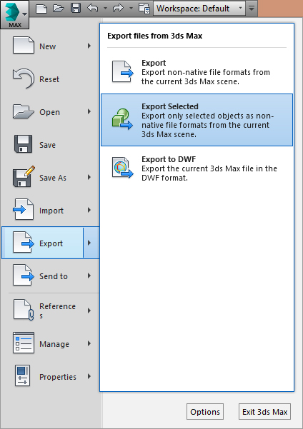
To exporting 3D models from Max follow these instructions:
1. When exporting models always select what You want to export and then “export – export selected”.
2. Set proper export settings.
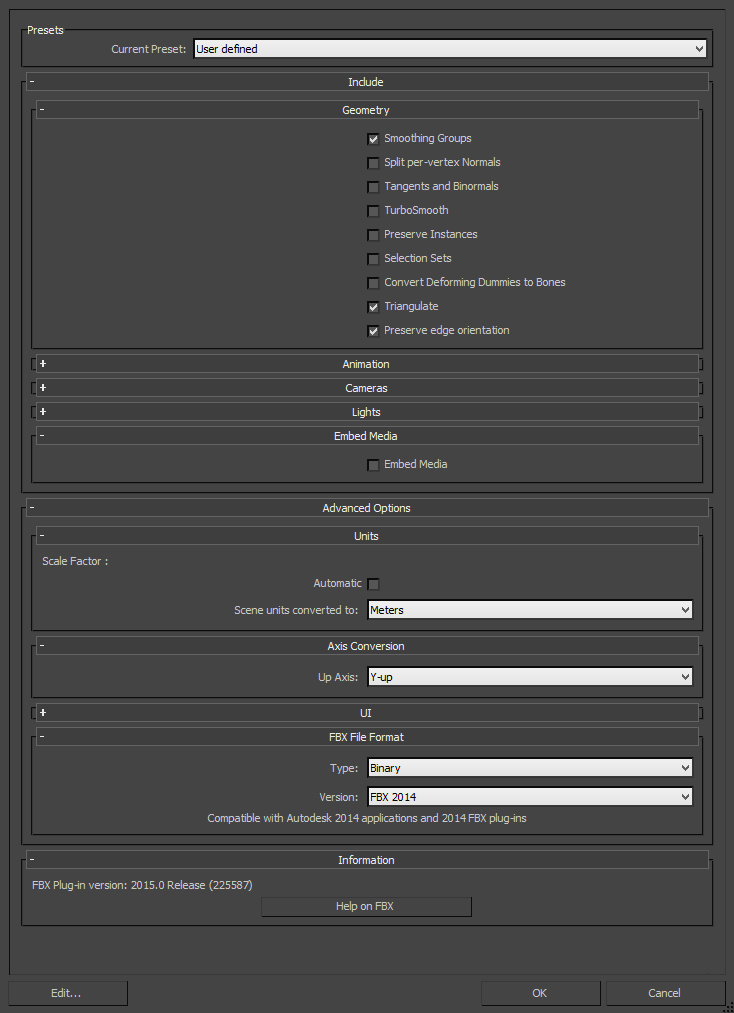
If You want to export .fbx use these settings on the picture:
Pay attention that “triangulate” has to be selected and up axis is “Y-up”. Otherwise the 3D model will be flipped in 3D Wayfinder.
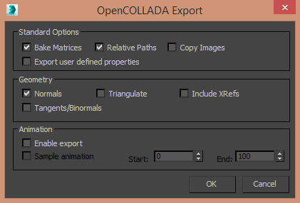
If You are exporting .dae then use only OpenCOLLADA exporter and these settings:
There are some minor differences with .dae and .fbx files. You just have to test, what suites better. All the materials can be tuned in 3D Wayfinder Administration panel (see the tutorial), so you don’t have to worry about ambient colors, transparency or other material properties.
We recommend that the whole building should not have more than 100 000 polygons. For kiosk applications (where it is possible to use better GPU-s) you can also have much larger models.
We have added built in cubemaps and cubemap reflection shader to FRAK WebGL engine. In addition reflection with cubemaps is efficient way to create reflective surfaces like glass or mirrors.
Also cubemap reflection is a rendering method. It means that reflective surfaces reflect the cubemap textures.
It will be available for 3D Wayfinder in near future. This will be the effective way to create large glass walls or buildings. It make them more realistic. It might be used also for expensive shopping mall floors.
Next feature in FRAK will be specular map to mark efficiently reflective areas.
Check out our new 3D Wayfinder platform demo. This will give you short overview of what you can do with 3D Wayfinder and what are our API capabilities.
The demo has following topics:
Moving 3D map with mouse cursor or touch screen.
Clicking on the map and getting location name and description.
Demo is accessible from the 3D wayfinder home page and can be opened also from this link:
[xyz-ihs snippet=”3D-demo”]
Demo is based on following javascript code. You are welcome to use it in your projects, your HTML should contain canvas with ID “map”. For more info please see 3D Wayfinder embedding tutorial.
var wayfinder;
var map;
var mapContainer;
var poiInfo;
var tutorialArea;
var currentStep = 0;
var STEPCOUNT = 3;
var originals = {};
var floors = {};

function mapResize(){
	if(wayfinder){
		cont = mapContainer.find(".map-area");
		map.attr("width", cont.css("width"));
		map.attr("height", cont.css("height"));
		wayfinder.resize();
	}
}

function runDemo(){
	map = $('#map');
	poiInfo = mapContainer.find("#poiInfo");
	tutorialArea = mapContainer.find(".tutorial-box");
	wayfinder = new Wayfinder3D();
	wayfinder.options.assetsLocation = '//static.3dwayfinder.com/shared/';
	wayfinder.open("1a07bdc53edb3828f390bc9af7281585");
	setTimeout(mapResize, 150);

	wayfinder.cbOnProgress = function(percentage){
		$("#progression").css('width', percentage * 100+'%');
	};

	wayfinder.cbOnDataLoaded = function(){
	    mapContainer.find(".loading-screen").hide(100);
	};

	wayfinder.cbOnMapReady = function(){
		removeAllFunctionality();
		setText(0);
		stepTutorialButtons(0);
	};
}

function stepTutorialButtons(step) {
	var prev = tutorialArea.find(".tutorial-prev");
	var next = tutorialArea.find(".tutorial-next");

	if (prev.text() && step === 0)
		prev.text("").off("click").css("cursor", "auto");
	else if (!(prev.text()) && step !== 0)
		prev.text("<").click(previousStep).css("cursor", "pointer");

	if (next.text() && step === STEPCOUNT)
		next.text("").off("click").css("cursor", "auto");
	else if (!(next.text()) && step !== STEPCOUNT)
		next.text(">").click(nextStep).css("cursor", "pointer");
}

function removeAllFunctionality() {
	if (wayfinder) {
		if (wayfinder.poiController) {
			originals.onPOIClick = wayfinder.poiController.onPOIClick;
			wayfinder.poiController.onPOIClick = function(poi, position, event) {};
		}
		originals.cbOnPOIClick = wayfinder.cbOnPOIClick;
		wayfinder.cbOnPOIClick = function(poi) {};
	}
}

function setText(step) {
	var keep = tutorialArea.find(".tutorial-text").find(".keep");
	if (keep.length)
		keep = keep.detach();
	switch (step) {
		case 0:
			tutorialArea.find(".tutorial-text").text("Click and drag on the map to move or rotate.");
			break;

		case 1:
			tutorialArea.find(".tutorial-text").text("Click on a location for more info.");
			break;

		case 2:
			tutorialArea.find(".tutorial-text").text("Click on a button to show that floor.");
			break;

		case 3:
			tutorialArea.find(".tutorial-text").text("Click on the button to show the path between two random locations.");
			break;

		default:
			break;
	}
	if (keep.length)
		tutorialArea.find(".tutorial-text").append(keep);
	stepTutorialButtons(step);
}

function addFunctionality(step) {
	switch (step) {
		case 1:
			if (wayfinder && wayfinder.poiController) {
				wayfinder.poiController.onPOIClick = originals.onPOIClick;
				wayfinder.cbOnPOIClick = function(poi) {
					poiInfo.show(100);
					poiInfo.find(".title").text(poi.getName("en"));
					var poiDescription = poi.getDescription("en");
					if (poiDescription)
						poiInfo.find(".description").text(poi.getDescription("en"));
					else
						poiInfo.find(".description").text("");
				};
			}
			break;

		case 2:
			poiInfo.hide(100);
			poiInfo.find(".title").text("");
			poiInfo.find(".description").text("");

			if (wayfinder) {
				var showFloor = function() {
					var f = $(this).attr("data-floor");
					if (f in floors)
						wayfinder.showFloor(floors[f]);
				};
				var fs = wayfinder.building.getFloors();
				tutorialArea.find(".tutorial-text").html("<div class='keep'></div>");
				var floorsMenu = tutorialArea.find(".tutorial-text").find(".keep");
				for (var i in fs) {
					if (fs[i] && fs[i].showInMenu) {
						floors[i] = fs[i];
						var button = $("<button data-floor='"+i+"'>"+fs[i].getName("en")+"</button>").click(showFloor);
						floorsMenu.append(button);
					}
				}
			}
			break;

		case 3:
			if (wayfinder && wayfinder.logic) {
				var randomPath = function(times) {
					if (typeof times !== 'number')
						times = 1;
					if (times > 9)
						return;
					var poiList = wayfinder.pois;
					var poiIDs = [];
					for (var i in poiList) {
						poiIDs.push(i);
					}
					var rand1, rand2;
					while (!rand1 || !(poiList[rand1].getNode())) {
						rand1 = rand2 = poiIDs[Math.floor(Math.random() * poiIDs.length)];
					}
					while (rand2 == rand1 || !(poiList[rand2].getNode())) {
						rand2 = poiIDs[Math.floor(Math.random() * poiIDs.length)];
					}
					rand1 = poiList[rand1].getNode();
					rand2 = poiList[rand2].getNode();
					try {
						wayfinder.logic.showPath(rand1.id, rand2.id);
					}
					catch (e) {
						// Try again
						randomPath(times + 1);
					}
				};
				tutorialArea.find(".tutorial-text").html("<div class='keep'></div>");
				var area = tutorialArea.find(".tutorial-text").find(".keep");
				var pathButton = $("<button>Show random path</button>").click(randomPath);
				area.append(pathButton);
			}
			break;

		default:
			break;
	}
}

function removeFunctionality(step) {
	switch (step) {
		case 1:
			if (wayfinder && wayfinder.poiController) {
				wayfinder.poiController.clearHighlights();
				poiInfo.hide(100);
				poiInfo.find(".title").text("");
				poiInfo.find(".description").text("");
				wayfinder.poiController.onPOIClick = function(poi, position, event) {};
				wayfinder.cbOnPOIClick = function(poi) {};
			}
			break;

		case 2:
			tutorialArea.find(".tutorial-text").find(".keep").remove();
			break;

		case 3:
			addFunctionality(2);
			break;

		default:
			break;
	}
}

function previousStep() {
	if (currentStep === 0)
		return;
	removeFunctionality(currentStep);
	currentStep--;
	setText(currentStep);
}

function nextStep() {
	if (currentStep === STEPCOUNT)
		return;
	currentStep++;
	addFunctionality(currentStep);
	setText(currentStep);
}

$(function(){
	mapContainer = $("#demoMap");
	$(".home-video").click(function () {
		mapContainer.show(100);

		if(!wayfinder)
			runDemo();
		else
			wayfinder.engine.run();

		$(window).resize(mapResize);
	});
});
Preview of Inserting External 3D Models to Floor Plans
June 17, 2015
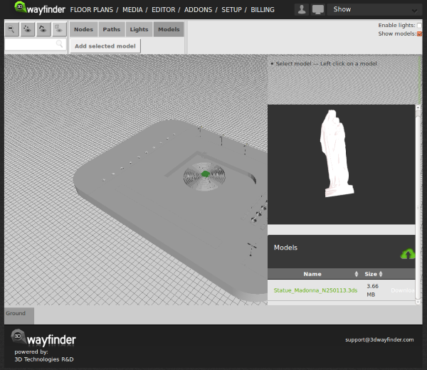
Currently we are developing features to insert external 3D models to floor plans. With this it would be possible to add these “little details” (like escalators, benches, trees or even cars). That make the floor-plans look realistic. The best thing is, that it doesn’t require any 3D modelling skills. So all our users can detail the floor plans by themselves.
3D object library can be opened in Editor window with object thumbnails:
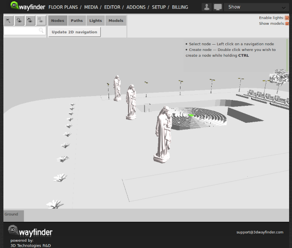
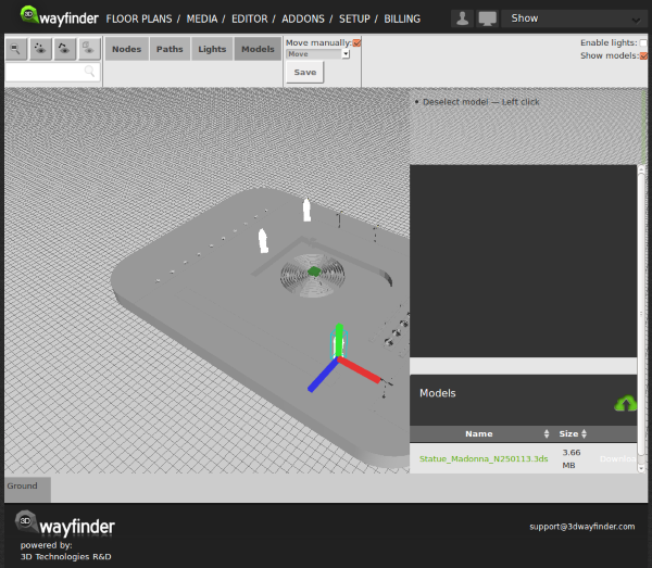
Added objects appear on the 3D scene. The good part here is, that the same model can be used inside the scene many times. Therefore it doesn’t increase the downloadable model sizes as each model will be loaded only once.
With external 3D models. We will definitely provide common library of models we are using to detail the floor plans. For example these will include trees, cars, different indoor plants, escalators, tables, stairs and so on. See our user manual.